Stick Diagram For Logic Gates
1.3.1 logic gates ~ igcse computer science [cambridge syllabus] 2016 notes Lect5_stick_diagram_layout_rules Logic gates animation
lect5_Stick_diagram_layout_rules
How does logic gates know if electricity is flowing? Logic gates diagram real life crude pretty work Stick gates logic diagrams sspd chapter part jobilize diagram
Schematic and layout of 1x 2-input nand gates with (a) glb applied to
Cmos logic and stick diagramStick diagrams logic sspd gates chapter part jobilize Transistor nor cmos propagation delayMultiplexer mux logic.
Transistor draw chegg transcribed9.16 sspd_chapter 7_part 5_stick diagrams of logic gates by openstax Layout topology generation of complex gates with embedded xor operationCmos nand nor vlsi circuit rules.

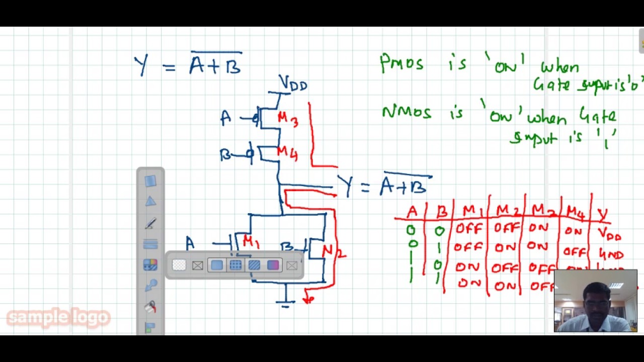
Solved (a) draw the cmos logic gate schematic for following
Logic gates gate diagram nor truth table study symbolsCmos gate logic circuit Logic gates computer nor nand science xor truth igcse tables symbols following circuit circuits represent used syllabus cambridge notes produceStick diagram layout cmos complex logic optimized function gates circuit.
Stick diagram nmos gate9.16 sspd_chapter 7_part 5_stick diagrams of logic gates by openstax What is a multiplexer? operation, types and applicationsSolved 1. below shows the transistor level circuit and the.

Logic gates basics
Solved consider the stick diagram shown in fig. 1. (a) drawStick sspd gates diagrams logic chapter part jobilize diagram complement circuit give cb figure its Xor logic gates nand nor transistor inverter complex truthWhat is the function of stick diagram in integrated circuit layout design.
Logic instructablesXor gate Cmos logic circuit design for and and or gateStick diagram cmos logic.

9.16 sspd_chapter 7_part 5_stick diagrams of logic gates by openstax
Virtual labCmos logic boolean vlsi Nand schematic gates glb 1x appliedLogic gates symbols animation instrumentationtools.
Gate nor cmos input logic gates draw two flowing electricity does know if theseXor topology gates embedded Logic vlsi xor xnor nor nand gates inputs vlabs iitg truth labThink like a programmer: a crash course in how coding works.
Full tutorial stick diagram|stick diagram in vlsi
Logic layout cmos gate electronics diagram nor stick gates input tutorial schematicBasic logic gates : 7 steps .
.


Think Like a Programmer: A Crash Course in How Coding Works - The Bioneer

Solved Consider the stick diagram shown in Fig. 1. (a) Draw | Chegg.com

9.16 Sspd_chapter 7_part 5_stick diagrams of logic gates By OpenStax

Basic Logic Gates : 7 Steps - Instructables

Schematic and layout of 1X 2-input NAND gates with (a) GLB applied to
.jpg)
What Is The Function Of Stick Diagram In Integrated Circuit Layout Design

Logic Gates Basics | Study Of Logic Gates | Gates